What this project is about
A modern breadboard (aka, "solderless breadboard") is a special board with connections 0.1 inch apart (the distance between chip pins) and horizontal busbars linking the connections underneath. The idea is that you can insert your component leads to make a circuit without having to etch a printed circuit board, and without have to solder a bunch of test components together. Here's a picture of a typical breadboard with a test circuit installed:
Breadboards are nice, but they can be very expensive. But let's ask one very obvious question: why are they called breadboards? Well, the answer will tell us everything we need to know about how to make our own, without spending a lot of money.
The origin of the breadboard (maybe)
Again, we start with a board. Wood is relatively non-conductive, especially for the kind of voltages you'll encounter in electronics. It makes a naturally-insulated platform. And what kind of small boards were readily available at little cost? Well, bread boards, of course. You can pick up some of the history at adafruit (an excellent place to get components and supplies at reasonable prices, by the way).
In the next few days, we're going to make an old-fashioned breadboard, using just stuff I can find around the farm. I already have 1.25 inch finishing nails, and there's wire all over the place out here, ripped out of previous installations and saved.
Side-note: the farmhouse where I live was built by Birdie and Robert Stewart -- my wife's grandparents -- back in 1957. Along the way, lots of wire of various types and sizes was installed, de-installed, and then left around wherever it fell. Your typical third-hand owner would just throw all that stuff out, but we have a motto for Birdie's Farm, or as we call it, "Birdie's Nest:" Save everything. You never know where you may be able to use something.
Using the board we have
There's no reason not to use the board we have; otherwise, we'd have to attach a second board in some kind of removable way, and that just doesn't seem necessary. So here we are with a hammer, some relatively short finishing nails, and a bit of time on our hands.
You can make the grid as big as you like. In this case, I made it big enough to build some serious circuits, but small enough to leave room for other work on the same board.

And in case you're wondering, the nails work fine:
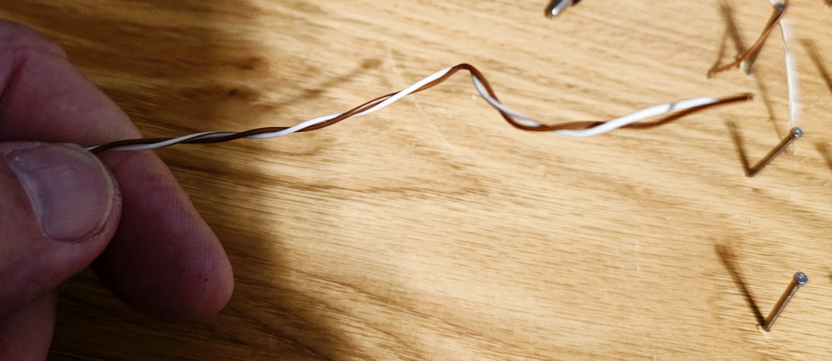
Now, I'm going to need some wire to make this work. I have some jumper wires, and I can use those, too. But I remembered that there's a whole lot of old phone wire that the landline company left when that device went away. Let me just grab some.
And, a bonus! It's twisted pair, so every wire is like having two jumpers of whatever length I want.
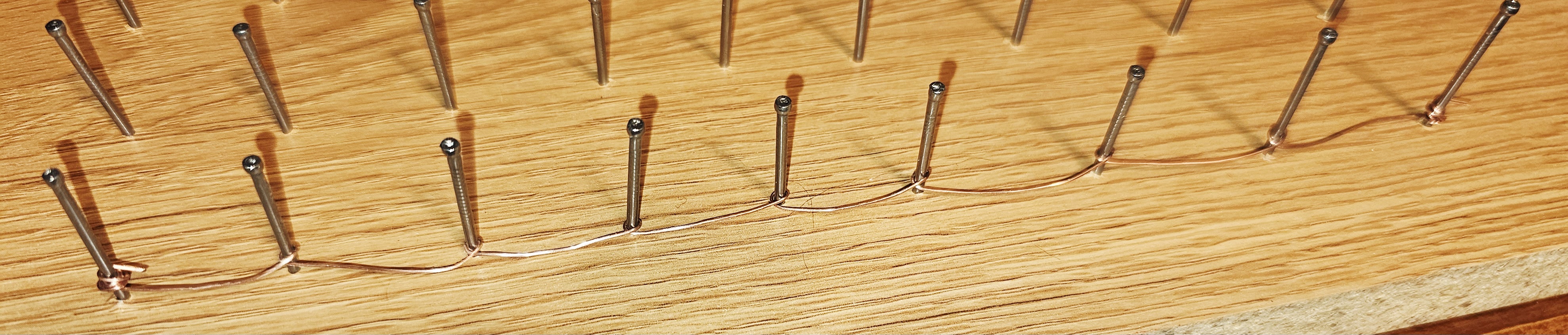
I'm not going to build a circuit to prove the board (I'm certain it will work), but I will wrap a couple of busbars for the battery rails. All the rest of the connections will be made on the fly.
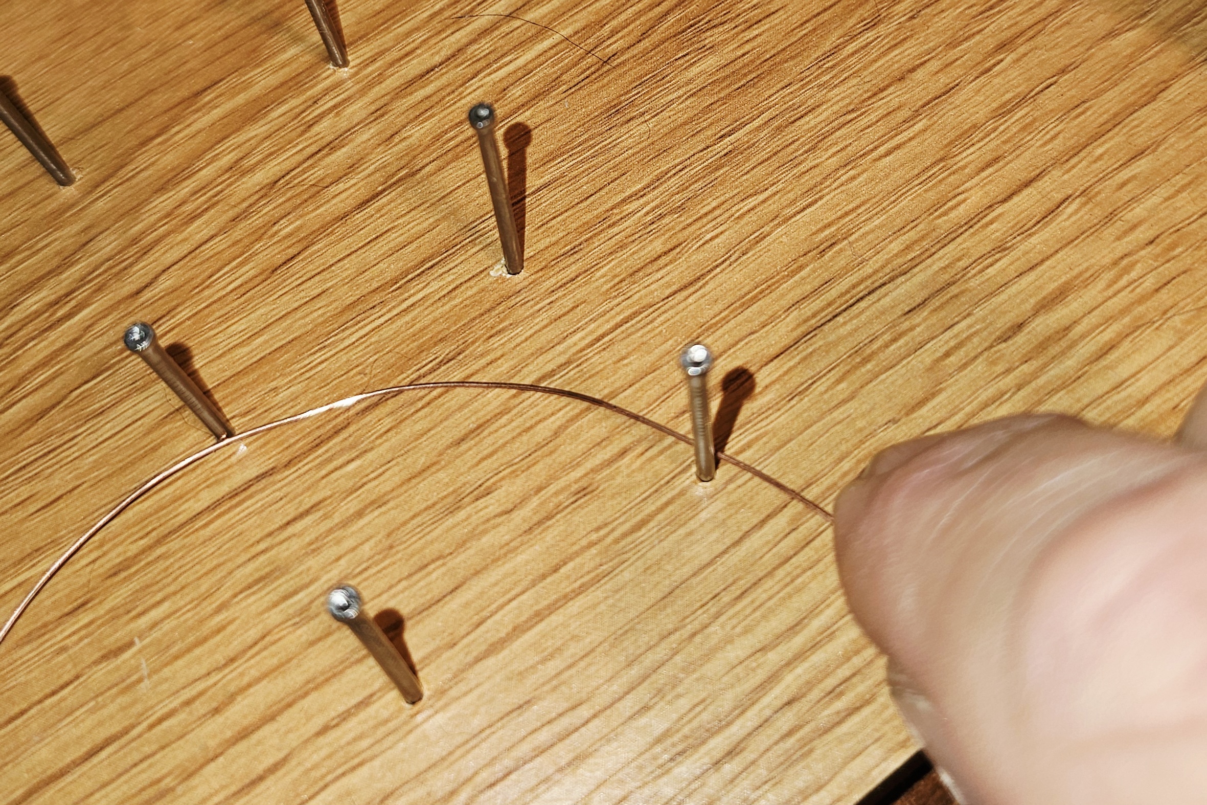
A little careful, hand-wrapping of wire, and voila! We have a busbar, or a battery rail, if you prefer.
Side-note: one of my power classes in undergraduate electrical engineering had 4080V busbars running around the room near the 15-foot ceiling. You had long wooden poles with metal hooks on the end to make your connections. Our professor was a real champ. The labs were from 6-10pm, and he would always bring enough chicken for everybody, and then warm it by briefly laying it across the busbars.
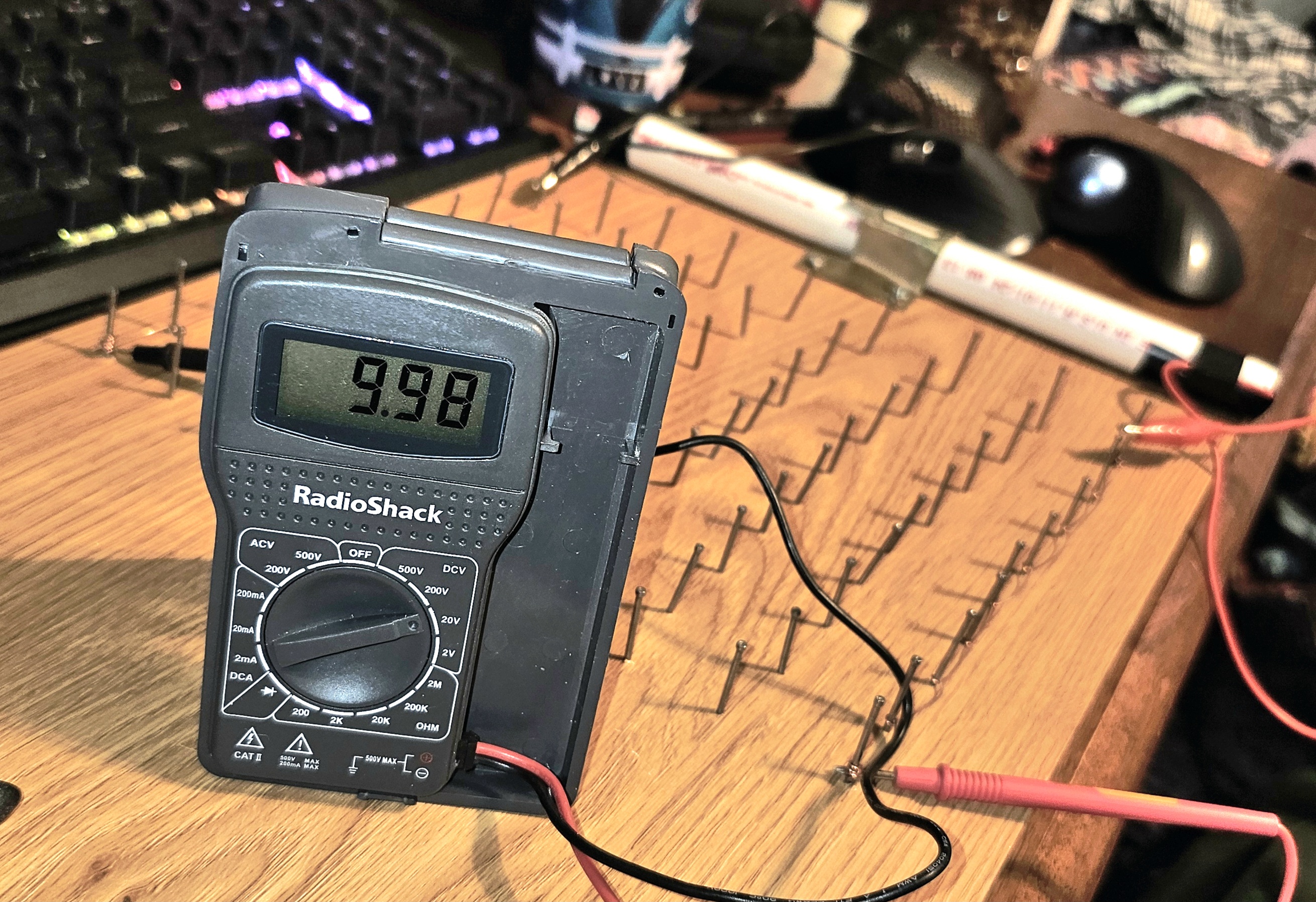
But staying with the story, you might wonder if the nails and wire cause any voltage drop. Nope. I made random measurements between several pairs of nails, and always got 9.97 or 9.98 volts, which has been the consistent output of our RBPS. I took this one picture to prove it. Pretty nice. Note that we are going to have to build some regulators, but I've got diodes, so no biggie.
I guess that's a wrap, but I think I am going to insert a few simple circuits into the list before we get to the voltmeter. We're all going to need some practice with our DIY breadboards.